Hydraulic compensating chuck for irregular, out-of-round and uneven workpiece surfaces.
Compensating Hydraulic Chuck with Floating Jaws
KORRETTO compensating hydraulic chuck with floating jaws is designed for workpieces that cannot be held evenly by a standard rigid jaw chuck. The floating jaw structure allows the clamping points to adapt to uneven, irregular or out-of-round surfaces, helping improve contact distribution on castings, forged blanks and workpieces with non-uniform outside profiles.
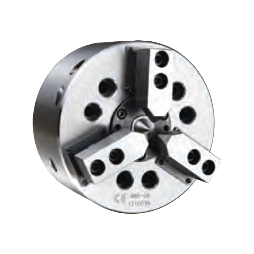
Product Overview
This compensating hydraulic chuck is used when the workpiece surface is not stable enough for conventional jaw clamping. The floating jaw mechanism allows the jaws to compensate within the chuck structure, so the clamping points can contact the workpiece more evenly.
It is suitable for CNC lathe workholding, special fixtures and production applications where the workpiece blank varies from part to part. It should be selected according to the workpiece shape, locating surface, clamping force, jaw stroke, machine spindle interface and required machining accuracy.
Key Features
| Feature | Description |
|---|---|
| Floating jaw compensation | The jaw mechanism can adapt to uneven or irregular workpiece surfaces. |
| Hydraulic actuation | Supports controlled clamping and release through a hydraulic chuck system. |
| Better contact on rough blanks | Useful for castings, forged blanks and out-of-round workpieces. |
| Special workholding use | Selected when standard hydraulic chucks cannot contact the part reliably. |
| Custom jaw potential | Jaw contact surfaces may need to be matched to the workpiece shape. |
Typical Applications
- Castings and forged blanks
- Out-of-round workpieces
- Irregular outside profiles
- Rough blanks before finish machining
- Workpieces requiring compensated jaw contact
- CNC lathe special clamping projects
Technical Data and Dimensions
Use the drawing and parameter tables to check chuck size, spindle nose, jaw stroke, hydraulic force, clamping force, maximum speed, mounting dimensions and workpiece compatibility. The values must be checked together with the machine spindle, drawbar and hydraulic cylinder conditions.
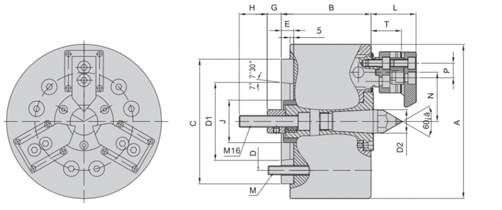
Use this drawing to confirm installation dimensions and technical parameters.
| Model | Spindle Nose | A | B | C (H6) | D | D1 | D2 | E | G | H | J | L | M | N | P | T |
|---|---|---|---|---|---|---|---|---|---|---|---|---|---|---|---|---|
| 3BD-06 | A5 | 168 | 116 | 140 | 104.8 | 82.56 | 24 | 15 | 4-20 | 38 | 50 | 52 | M10*120 | 55 | 14 | 34 |
| 3BD-08 | A6 | 210 | 127 | 170 | 133.4 | 106.38 | 32 | 17 | 9-29 | 38 | 58 | 61 | M12*125 | 67 | 20 | 41.5 |
| Model | Spindle Nose | Plunger Stroke (mm) | Jaw Stroke (mm) | Max. Pull kN (kgf) | Max. Clamping kN (kgf) | Max. Speed (r/min) | Clamping Range (mm) | Compensation Range (Diameter, mm) | Moment of Inertia (kg·m²) | Weight (kg) | Matching Cylinder | Max. Pressure MPa (kgf/cm²) |
|---|---|---|---|---|---|---|---|---|---|---|---|---|
| 3BD-06 | A5 | 16 | 13 | 14.7 (1500) | 25.0 (2550) | 3500 | 6–35 | 5 | 0.2 | 13 | 100 | 2.1 (21) |
| 3BD-08 | A6 | 20 | 18 | 19.6 (2000) | 34.3 (3500) | 3000 | 16–65 | 6 | 0.5 | 22 | 100 | 2.8 (28) |
Selection Notes
- Confirm whether the workpiece surface is irregular, out of round or inconsistent between blanks.
- Check the locating reference before selecting the clamping points.
- Review jaw stroke, compensation range, hydraulic force and maximum speed.
- Confirm spindle nose, drawbar connection and cylinder compatibility.
- For thin-wall or easily deformed parts, also compare diaphragm chucks and rubber-flex collets.
FAQ
What is a compensating hydraulic chuck used for?
It is used for workpieces with uneven, irregular or out-of-round surfaces where a standard jaw chuck cannot provide stable and even contact.
Is this the same as a floating-jaw chuck?
Some suppliers may describe this type of workholding as a floating-jaw chuck. On this page, we use “compensating hydraulic chuck with floating jaws” to describe the structure more clearly: the jaws can adapt to uneven or irregular workpiece surfaces during clamping.
When should I choose this chuck instead of a standard hydraulic chuck?
Choose it when the workpiece blank varies in shape, has rough or uneven surfaces, or needs the jaws to compensate during clamping.
Can this chuck be used for castings and forged blanks?
Yes. Castings and forged blanks are common applications because their outside surfaces may not be uniform before machining.
What information is needed for selection?
Provide the workpiece drawing, blank condition, clamping surface, locating reference, material, machine model, spindle nose, hydraulic cylinder data and required machining accuracy.